

Flex Circuit PCBs
The PCB’s that you use in your electronics devices are often made of a combination of rigid and flexible sections. Rigid sections provide stability and structural support while flexible circuits allow for the device to bend, twist, fold and flex. This flexibility is crucial for the device to function properly and allows it to withstand vibrations that would otherwise cause wire connections to fail. These benefits are why a lot of the newer devices are starting to use flex circuits.
However, you’re probably wondering how are flex circuit pcb manufactured? The answer to this question is quite complex and involves several different processes. First, the substrate material is prepared. This is done by cleaning the surface to create a clean, smooth surface for the circuit pattern to be printed on. Then the photolithography process begins. This is a critical step in the manufacturing of a flex PCB because it is during this process that the circuit patterns from the design layout are transferred to the substrate material.
Next, a layer of copper is deposited and chemically etched onto the surface of the substrate material. This is referred to as the “cladding” phase. The amount of copper deposited can vary from very thin (under.0001”) to thicker than standard PCB thickness.
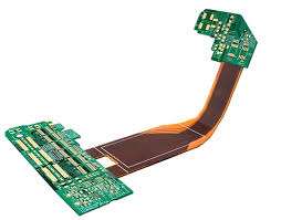
How Are Flex Circuit PCBs Made?
After the cladding process is complete, a layer of protective coverlay material is applied to the conductive surface of the flex. This protects the traces from environmental factors such as moisture, dust and physical damage. This protective layer is typically a polyimide or polyester film.
A thin layer of adhesive is then applied to the flex and the rigid section of the board. This is used to bond the two together. It is also a good time to inspect the boards for any defects such as voids or sharp edges that need to be repaired.
Once the adhesive is dry, the flex and rigid sections of the circuit are then drilled using precision drilling systems. This is a very critical process because any kinks or creases in the production panels can lead to electrical failures and loss of product reliability.
Finally, the flex circuit is combined with the rigid sections of the circuit and they are plated through and through with copper in much the same way that a double-sided rigid board is plated through. The finished product is now ready to be soldered into your device. This process requires careful handling to ensure that the flex circuit doesn’t get damaged or twisted in transit.
This is why it is important to follow well-defined manual handling and shipping methods. The result is a rigid-flex circuit that can be bent, folded and flexed while maintaining its electrical integrity. This gives the designer tremendous flexibility in device form factor, size and weight compared to traditional rigid PCBs. The resulting device is smaller, lighter and more functional than a similar rigid-only circuit. This can result in significant cost savings for the manufacturer and the end-user.