

Ensure Durability in Flex Circuit PCB Designs
The material used in rigid and flex circuits is important in their ability to withstand mechanical stress and bending. It is also important to consider the design and assembly process when determining the durability of the circuit board. These factors need to be carefully modeled in order to ensure the integrity of the final product when subjected to environmental stressors such as heat, moisture, chemicals, and shock and vibration.
Rigid-flex PCBs consist of a base substrate, typically a woven fiberglass impregnated with epoxy resin, and copper traces that conduct current and transmit signals. The conductive copper traces are the heart of the PCB, and they are what determines the ability of the circuit to bend and move with its environment. It is critical to select a durable material, such as a polyimide film like Kapton, and properly plan the flex circuit’s flexing zones during the design stage.
In addition to the base material, the copper foil thickness and adhesive type are also important considerations. Thicker foils and adhesives offer more strength, while thinner foils are less flexible. The use of pressure-sensitive adhesives (PSA) offers an easy and affordable option to bond layers of the PCB together. However, PSAs are not recommended for flex circuits that will be subjected to dynamic bending or movement.
Another factor to consider when choosing a flex circuit pcb is the etching process. In the etching process, holes called vias are drilled through the copper foil to connect traces to other circuit layers. The copper is then exposed to photolithography, and the unwanted areas of the foil are chemically etched away to expose the conductive paths that were outlined in the PCB’s design software.
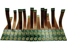
How to Ensure Durability in Flex Circuit PCB Designs
Conductors should always be routed perpendicular to the overall bend radius. This will eliminate stress points that may damage trace copper. Similarly, curved traces are preferable to angled traces, as harsh angles will reduce their longevity. Finally, it is important to stagger traces across layers to avoid l-beaming and the associated stress that can harm copper circuits.
Using proper fillets (or teardrops) at the intersections of pads and traces will reduce stress concentration spots and prevent cracking during bending. This is particularly important for flex circuits with multiple layers. In addition to minimizing stress, teardrops help improve etch yield and material strength and are appropriate when the pad diameter is larger than the connecting strand width.
It is important to be clear with the flex circuit manufacturer about the application and environment. If a flex circuit will only need to be bent once and left in a fixed position – such as in handheld ultrasound devices – the designer can be much more liberal with layer counts, the copper type and thickness and the number of plated through holes. But if the flex circuit is to be constantly moving, bending and rolling it will require a higher-grade RA copper that can stretch further before fatigue cracking. This will increase the cost, but it will also allow the flex circuit to endure far more bending and dynamic movement before failure occurs.